Controlling the Remote Mirror
by Larry Jett

|
|

|

Click pictures to enlarge
Should your restoration require the chrome plating of the superstructure supporting the remote controlled mirror, it will have to be removed and then replaced on the car post- plating. This is how it is done on a 1964 Chrysler. Attempt any other order than the following and you will be starting over.
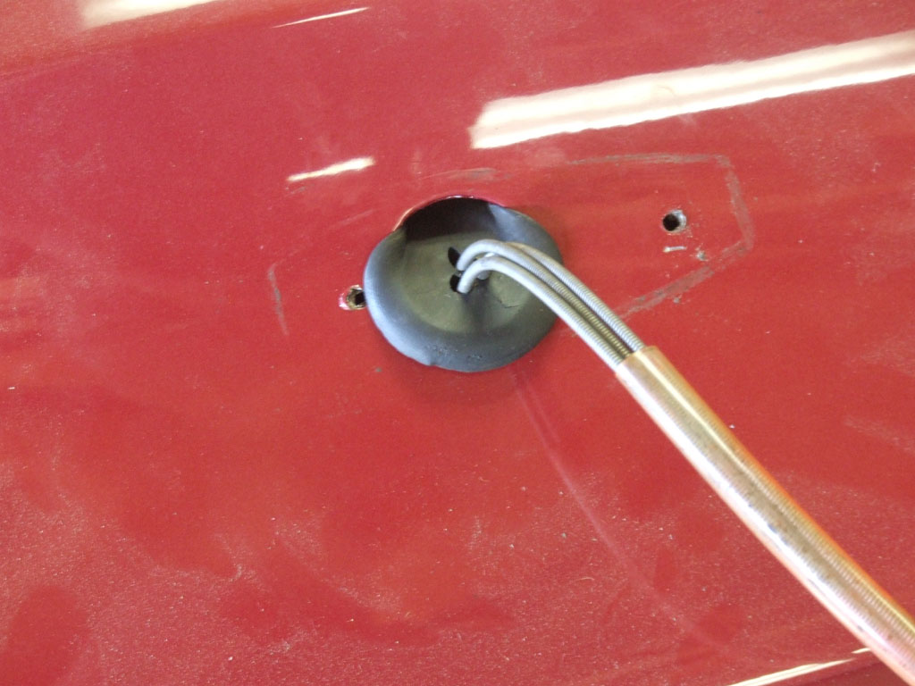 Release the toggle switch from the dash by unscrewing the locating nut with a screw driver and small hammer so as to rotate the nut counter-clockwise and then loosen the rubber pass-through grommet on the firewall. Pull the toggle switch and three cables into the engine compartment and then out past the fender hole after removing the two screws that locate the mirror to the fender. The firewall grommet must be persuaded to smooch through the fender hole with help of some needle-nose pliers. You now have all the parts removed from the car but none taken apart. Good time to study carefully or take a digital picture.
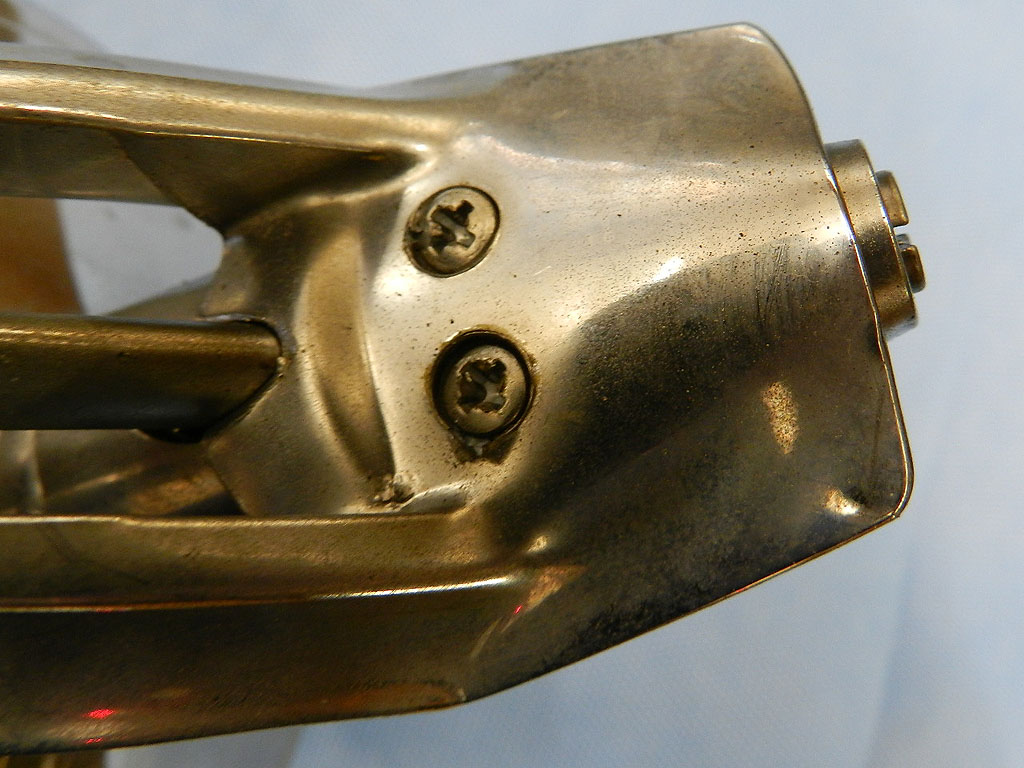
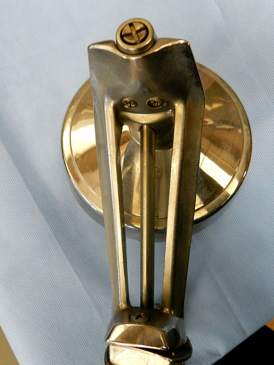
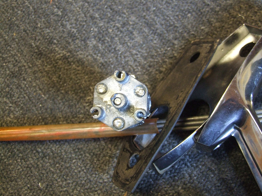
Remove the two screws locating the horizontal chrome from the vertical and the long screw locating the mirror head to the stand.
The wire and sheaths of the three cables are stouter than they appear. Notice that
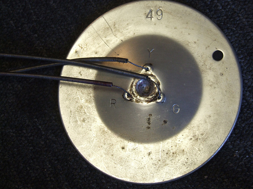
stamped on the mirror head are a R G Y.
Get some color device in Red, Green, Yellow and color up the cables to match the RGY on head (but you can skip this step if you only undue one of the three as mentioned below).
The toggle end also has RGY on the bottom end and you need to color up that end as well, both the toggle support platform and the wires. This insures that everything goes back in proper rotation as it came apart. Skip this step at your own peril.

The mirror head......soak the 3 cable to head junctions in your favorite brew to free rusted bolts and do the same at the toggle end as well. You now have to widen slightly the crimped slot that the cables are held tightly by but only for any one of the three at the mirror head end.
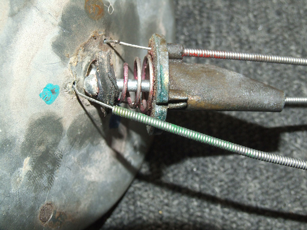 The other two can be left as is because if you have one free, you can remove the spring and ball end and proper clearance will be available for the reassembly later. All three of the toggle end have to be done. You are done widening and soaking when one is freed at mirror end and all are free at toggle end. Extract the sheath slightly from the slot cylinder so the interior wire can be slid up the slot and released from bondage at the head end (any of the three can be selected) and the button ends are all released from the three cells at Toggle Prison.
Cut slots with a razor blade on the inside dash side of the rubber grommet so the button end of the interior wire in each sheath-cable can be pulled through the rubber grommet with less trauma to the wire end buttons.
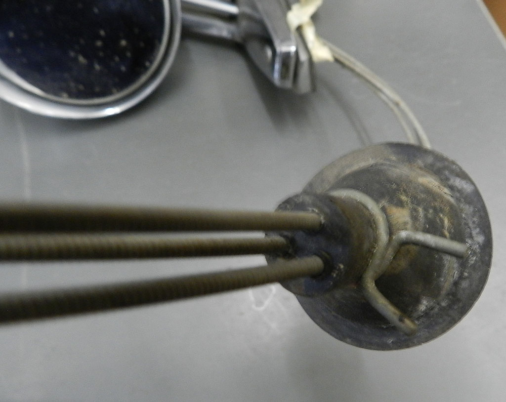
After the chrome is back, begin reassembly. Put all parts together as the expanded photo shows.
Snake the three cables through all parts and grommet before doing anything else. This is a very important sentence! Sequence: Grommet, plastic tube (if you find you had one) fender gasket, chrome angle locating base, chrome superstructure with the chrome tube that covers the cables and then the cables snaked through the bullet shaped end cap. Take a nap.
Attach the sheath and wire ends to the toggle switch in proper color order and then consider the mirror head end only after the toggle is finished. Reinstall the spring and ball and washer end between mirror head and three way platform. Attach the one wire removed at disassembly. There are locating bosses for the mirror head to mirror cover as well as the bullet end cap to mirror cover. Match these and place some paper towel wad under the mirror glass so as to hold it tight when mirror cover and glass are placed on a level surface as photo shows. This is a good time to double check that the three cables are snaked through every orifice correctly as they were when you first had the entire apparatus removed from the car but not yet disassembled.
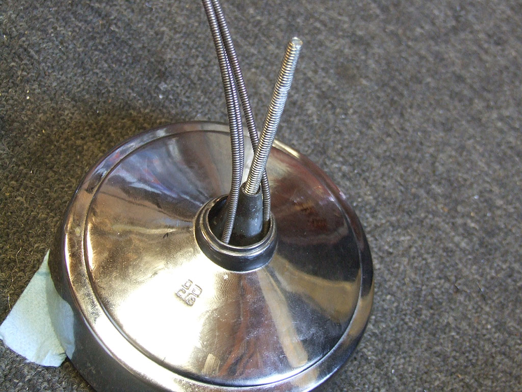
It will save time if you obtain a number 10 stud longer than the factory machine screw that holds the head to the superstructure. (see photos) Three inch length is good enough. Use it to line up the receiving hole surrounded by the cables
making a sharp bend where you can not see them.

When all in proper position, remove it and drop the factory machine screw straight down to the receiving hole. This is at least a half-hour time saver than trying to match the barely long enough factory screw to its destination where you can not see it.
Snake the toggle, grommet and plastic tube back through the fender hole and through fire wall and home again on the dash after proudly attaching your nicely chromed back-looker to fender.
Back