 |
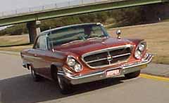
This disc brake conversion project was performed on my 1962 "300" Sport, using parts supplied by Magnumforce Racing in California. Here is a pictorial step-by-step of the process. |
by John Hertog (written sometime about 2000-2001)
|
This disc brake conversion project was performed on my 1962 "300" Sport, using parts supplied by Magnumforce Racing in California. Here is a pictorial step-by-step of the process. |
Please click here to view the conversion package as it come out of the box!
 |
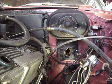
First order of business was removing the master
cylinder... now you will see that this car is equipped with an
over-and-under brake booster setup, from a 1960 Chrysler. I had to
perform this modification in order to equip the car with short rams, and
still retain the power brakes. I did not want to convert the car to the
300J / ramK remote booster system.
Also as part of this project, I decided to replace my steering box. You might notice it missing in the pictures. Having it off gave me easier access to things, but was in no way necessary to perform the conversion. You will notice that the left side exhaust manifold is also removed. This is in order to get the steering box out, as the cast iron headers I installed in this car interfered with that.
|
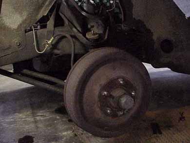 |
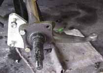
Here's the old drum brake setup. All further pictures
refer to the left (driver's) side of the car unless otherwise noted!
You will notice the forward-located attaching point for the brake hose. At this time, remove the drum, pull it off, disconnect the brake line at the frame, and remove the backing plate with all drum stuff still attached.
|
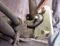
| This picture was taken from the rear looking forward. It shows the steering arm still attached to the tie-rod, after the backing plate was removed. Notice the 4 bolts that held the backing plate; the two longer ones, diagonally opposed, went thru the steering arm. Only the bottom/rear (long) bolt and matching castle nut will be re-used. All others can be discarded. Next step is to completely remove the steering arm by breaking it loose at the tie-rod. | 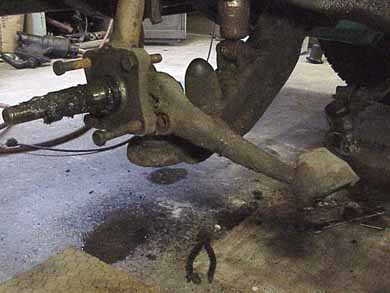 |
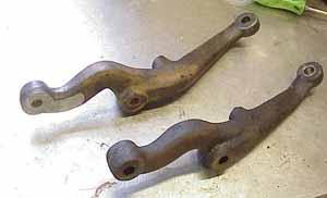 |
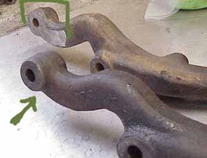
Now the only modification that you will have to make to the car is to the steering arm, as a little bit of metal has to be ground off where the arm and the adapter plate sandwich together on the spindle. On top, the finished product. On the bottom, what came off the car. The folks at Magnumforce had ground down the upper steering arm during the development of this project... but I had sent them a 1960 (long wheelbase) steering arm, which is slightly different than the one from my short wheelbase '62. Therefore I must modify my arm to match the other... The difference between the two arms is very subtle, but they are quite different indeed.
|
|
I have outlined the area that has been already been ground off on the uppermost arm . The arm on the bottom needs to be ground off so as to be flat with the body of the arm... just like the one on top. It's easy with a grinder... Please note that these are BOTH left side arms.... we're only working on the LEFT side of the car... .
|
|
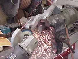 |
And here's the grinding in progress... Please remember to
wear eye protection. I used those nice glasses they gave us when we
toured the Toyota plant during our Spring 99 meet in Kentucky!
Grind until the protruding area around the bolt hole is flush with the body of the steering arm .
|
| Now time to install the Magnumforce Racing adapter bracket to the
spindle, together with the steering arm we just modified. Here's a view
of what that looks like when installed. The bracket is located IN FRONT
of the spindle.
The rear uppermost hole on the spindle will not be used. The rear bottom hole will have an original bolt and castle-type nut going through it, and the steering arm.
|
 |
 |
And here's what the backside looks like. We will use the bolts and self-locking nuts supplied with the kit to attach the bracket to the spindle. We will also tighten the remaining original bolt and nut at the bottom, rear corner. And that's the end of this part of the job. |
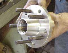
| Now is the time to prepare and assemble the hub / rotor assembly.
Step One involves inserting the lugs into the hub. Make sure you use the holes for the appropriate Mopar bolt pattern! Lugs supplied with this prototype kit are much too long... as you can see...
|
 |
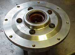 |
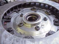
Then we install the inner bearing and seal, and also
attach the rotor adapter plate, held on by FIVE Torx-headed bolts.
YOU MUST MAKE SURE TO LOCTITE THESE BOLTS! |
| Now the rotor gets bolted to the adapter plate , and once again ALL BOLTS GET LOCTITE! | 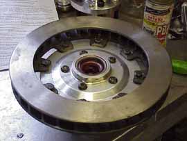 |
 |
Safety wire gets threaded through all the bolt heads, as shown. Don't want any of this stuff to come apart! I used 18 Ga. steel wire 'cause it was there, but you might want to go to lighter gauge stuff. |
|
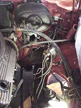
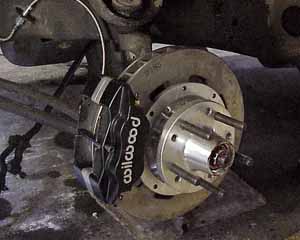
Grab the rotor/hub assembly, and place onto the spindle. You might have to very lightly run some 400 sandpaper on the seating surface of the rear bearing so that it will slip on. Install the front bearing, re-use the washer, nut, nut cover and install a cotter pin after tightening appropriately. Now install the caliper onto the adapter plate. Two nuts and bolts, with washers. The self-locking nuts go inside... that took me a minute or two to figure out. Tighten both. Then insert the brake pads, an easy task. Replace the center pin holding the pads in. And that's how far we got today. Added a brake hose (supplied) just for looks!
|
 |
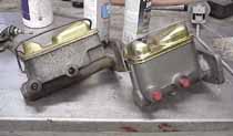
Pictured here are two different style master cylinders. Both came from NAPA,
both were ordered for a 1970 Chrysler with disc brake, and they are different!
One is much taller than the other. I will be using the shorter one because of
interference problem with the brake booster.
If you go back to the second picture of this series, you will see from the brake lines under the booster that my car had already been converted to dual circuit brakes (there are TWO brake lines visible where the master used to be) but of course this was still a drum/drum setup. I had installed an appropriate distribution block; but I had NOT installed a proportioning valve. For this project, I will keep my drum brake distribution block, and add the adjustable proportioning valve Magnumforce Racing supplied.