Panelescent Instrument Panel
and
Electroluminescent Power Supply Repair
by Carl Bilter
The 1960-62 Chrysler, 1960-63 Imperial, and 1966-67 Dodge Charger used an electroluminescent (a.k.a. Panelescent) power pack to operate the dash lighting. While some minor differences might exist in physical or electronic configuration, they are all operationally interchangeable. The example here is from an Imperial.
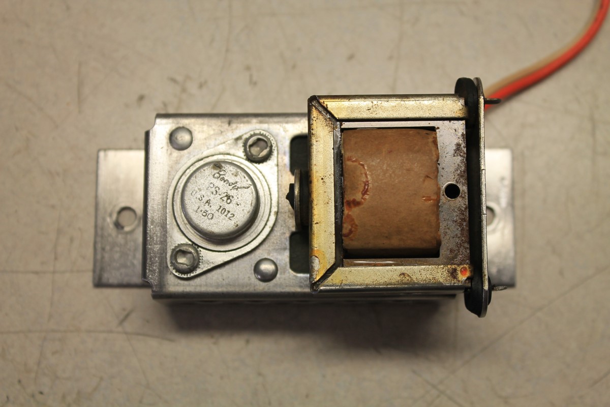
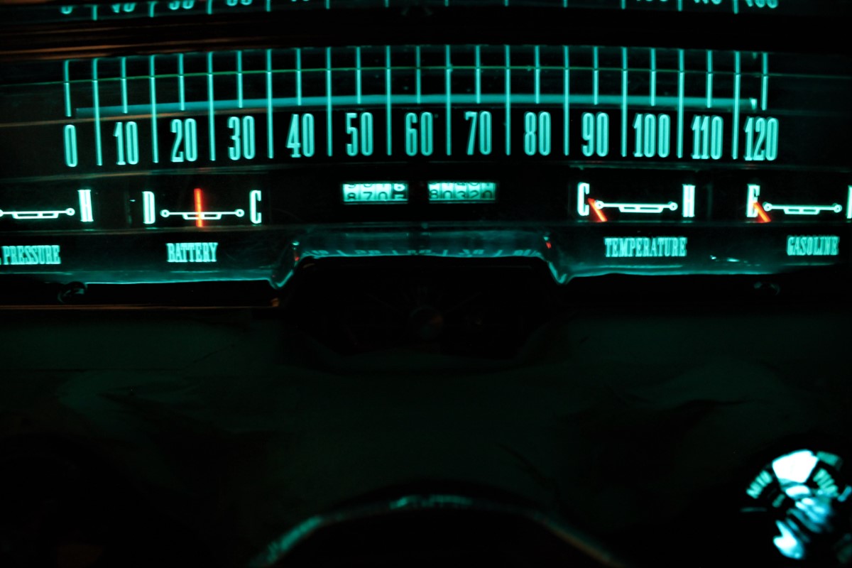
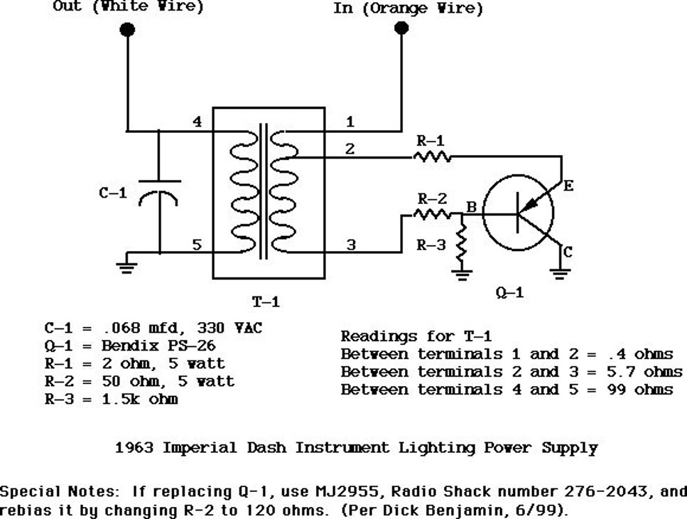
The electroluminescent dash instruments were powered by this device which is a transistor oscillator that converts the 12V D.C. battery input voltage to around 230 to 300V A.C. output voltage. The following circuit diagram shows that the circuitry is fairly simple. The orange wire receives the 12 volts D.C. from the battery when the headlight switch is pulled out. The white wire is the 230+ volts A.C. output to power the instruments. The power pack consists of a capacitor, 3 resistors, a transformer, and the power transistor.
When diagnosing electroluminescent dash lighting maladies, it is easy to determine whether the power pack or head light switch is at fault. The 60-62 Chrysler lighting has a bulb in the heater and shifter buttons. If you have no lights at the heater and shifter buttons, it’s probably in the head light switch at fault.
If you have heater buttons lit but no dash lighting then very likely it is caused by a fault or short in one of the
electroluminescent panels, which will kill all of the lighting
(gauges, clock and radio). The gauge dial pointers
might not light up as well, and this is very typical because the
extremely fine “litz” wire that connects to the gauge
pointer breaks over time. That said, a failed gauge pointer will not
kill the rest of the lighting.
If the dash lighting works, but is dim
or fades out quickly, then the problem is with the power pack.
Typically, the capacitor goes bad from age and replacing the
capacitor alone might restore full electroluminescent functionality.
That is good news because we DIY types can easily fix this problem
for only a couple dollars and avoid the need for sending out the unit
for a $100+ overhaul. All you really need is a good soldering iron,
some rosin core solder, and a good digital volt-ohm meter (I use a
Fluke Automotive meter).
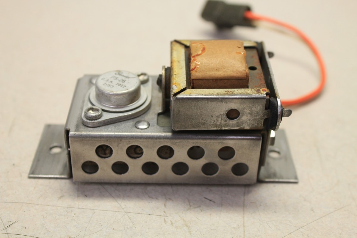
So, let's examine the electronic
components inside the power pack.

The transistor will be one of a couple types of Bendix PNP transistors that are no longer produced. In this example, it is a PS-26. There are modern replacements that will work but might require one of the resistor values to be changed. The transformer can be tested by checking the impedance as indicated in the schematic. Fortunately, both of these components are often still operational. In fact, the transformer almost never goes bad. That leaves the capacitor and three resistors. Always assume the capacitor is bad. The resistors can also go out of spec with age and heat, and so need to be checked with an ohmmeter as well. All of these parts are inexpensive and easy to find online at retailers such as Mouser or DigiKey. I like the Mouser web site and the $4.99 economy shipping. The shipping will cost more than the parts.
The capacitor (C1) in this unit is a .068uf (microfarad) unit rated at 330 volts A.C. Other power packs might have a .047uf or .05uf capacitor, but a value within 10% to 20% will be OK. What is critical is the voltage rating. Most capacitors are rated for D.C. voltage. Make sure to order a capacitor rated for at least 330V A.C. and preferably more such as 400V A.C. or higher. Do not use an electrolytic capacitor due to the nature of the oscillator circuit.
R1 is a 2 ohm 5 watt wirewound resistor with 10% tolerance. R2 is a 50 ohm 5 watt wirewound resistor without a tolerance spec (therefore, assume it is 20% tolerance). R3 is a 1500 ohm ½ watt carbon resistor with 20% tolerance. If these resistors test out within the tolerance spec, you can leave them alone, or just replace them anyway since you have the unit on the bench. To test R3, you will need to unsolder one of the two leads to get a valid reading. The other two resistors will test reasonably accurate within the circuit. In our example, we replaced the capacitor and two of the resistors as shown in the photo.

Each power pack will give a slightly different output reading in A.C. volts. A precise value isn't important. Anything between 230v and 300V A.C. is probably OK.
To be honest, it will be a lot more work removing and replacing the power pack in the car than it will be to repair the unit.
After reinstalling the refurbished power pack in the Imperial, we have beautiful, full brightness electroluminescent lighting, for a total repair cost under $2 plus shipping.