|
Letter
Car Radio Diagnosis and Servicing – a primer for DIY car guys
and gals –
by Carl Bilter and John Grady
During
300 letter car production from 1955 to 1965, Chrysler offered two
types of AM radios, the basic “5 button”
manual/pushbutton tune radio and the “7 button”
search-tune radio. In January of 1963, Chrysler began offering an
AM-FM manual/pushbutton tune radio as well. All radios were optional
equipment at extra cost. During this ten year time span the
electronic technology of the car radios evolved form vacuum tube
powered to a hybrid design (vacuum tube plus transistorized audio
output) to 100% solid-state (fully transistorized).
Most
of us DIY car guys and gals have a basic understanding of electrical
and electronic functions of our 300s as we have encountered issues
with wiring, alternators, voltage regulators and many other
components. We have successfully diagnosed issues and repaired,
restored or replaced these components before – and the car
radio is just one more such device. With just some basic knowledge
we can at least perform some diagnosis and repair, and in many cases,
restore a reasonable level of performance to what might have been
thought a “dead' or poorly functioning radio.
Many
folks today prefer to just add some modern radio component hidden in
the glove compartment, or have the radio gutted and have modern
circuits installed in order to receive FM stereo, XM satellite, allow
MP3 or Bluetooth connectivity, etc. “Modernization” is
fine but outside the scope of this page. Fortunately there are
still professional “radio guys” around who will restore
vintage car radios, but a DIY car guy can also do some basic radio
diagnosis and servicing as well.
Testing
in the vehicle:
If
the radio in the car doesn't even power up, then obviously check the
radio fuse in the fuse block first. If the fuse is good but the
radio seems dead then there could be major issues and it must be
removed from the car and taken to the bench (more about bench testing
later). But if the radio seems to “power up;” that is,
the dial light works when the set is turned on, or the radio makes a
humming or static noise, or better yet actually receives a station
however faint or distorted it might be - then the radio actually does
work, and the first step is to perform a few simple tests with the
radio in the vehicle.
Speaker: check that the front (dash) speaker is connected. Even if
the cone is torn it will likely still work, albeit poorly. If the
car radio is 1957 or newer (i.e. has transistorized audio output),
DO NOT operate the radio without a speaker connected, as it can
damage the transistors. If you are going to service the radio, go
ahead and get new speakers if they are still the original Mopar
“Deluxe” units. Those original speakers were “deluxe”
in name only! Most of the radios were designed to work with 3.2 ohm
to 4 ohm speakers. Most modern car speakers are 4 ohm. You can use
8 ohm speakers as well. 8 ohm speakers will not play as loud but
offer a little less distortion. You don't need a high power
handling speaker with a huge magnet. The stock radios do not have
high output amplifiers, nor are they really high fidelity like a
modern stereo, although the radios will sound better with a decent
speaker. AM radio theoretically has a maximum audio range of
20Hz-10khz, although a lot of AM radios (and some broadcasters)
cutoff above 5khz. However, these vintage car radios had better
midrange and treble response than the modern AM sections of car
radios which have poor frequency response.
Rear speaker connection: Most of the Mopar radios have a rear
speaker socket on the back of the radio for the optional rear
speaker. If your car has a rear speaker, the radio should have the
special rear speaker wiring harness with a 4-pin plug connected to
the rear speaker socket. The plug has 2 pins spaced a little wider
than than the other two; therefore, it only can be inserted one way.
If your car only has a front speaker, then a U-shaped jumper must
be inserted in the rear speaker socket or else the front speaker
will not play. If the jumper is missing, the radio will power up
but make no sound! Many of our radios have been transplanted from
other vehicles at some point in the life of the car, and if the
radio came out of a car with a rear speaker and is installed in a
convertible, for example, which only has a front speaker, this
jumper might be missing. Not only must the jumper be present, it
must be installed correctly, which varies by model of radio! On the
5 button radios, the jumper is inserted in the the two wider-spaced
pins on the rear speaker socket, and sits horizontally. The wider
pins are usually the bottom two pins, but on the 1963-64 AM-FM sets
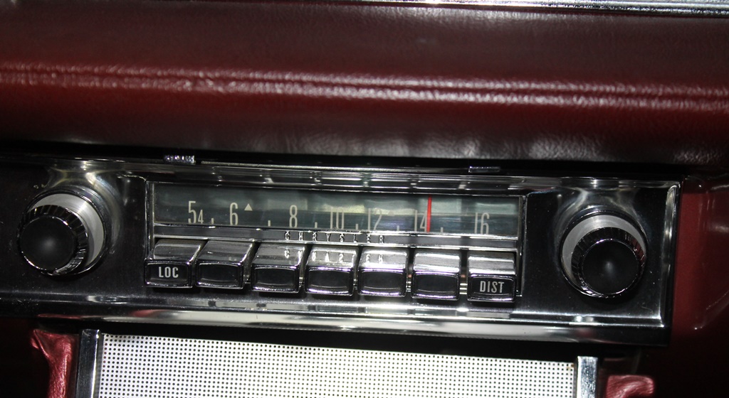
they are the top two pins. The early 60's 7 button radio has a five
pin rear speaker socket, and the jumper is inserted at a 45 degree
angle between pin #3 and the center pin, as seen in the photo below.
I wonder how many “dead” radios are really not dead;
they are just missing the jumper! You can make a jumper from #12
solid building wire. Make sure that it fits very securely (not
loose). Depth is not very critical. Here is a photo of the jumper
correctly installed in a 62 seven button radio:
Antenna Cable: check the antenna cable that plugs into the back of
the radio. Disconnect the cable, and perform a continuity test
between the cable and the antenna. Use your ohm meter and clip one
lead on the antenna and the other lead to the center male pin of the
antenna cable that plugs into the radio. You want to see close to
zero ohms, or at least under 10-20 ohms (a rear mounted antenna has
a long cable and you might see higher resistance than with a front
mounted antenna). There is a very fine antenna wire that can open
at the mast; so you want to make sure that the antenna and cable are
actually functional. If the antenna is OK then make sure that the
antenna cable is securely seated in the antenna socket in the back
of the radio.
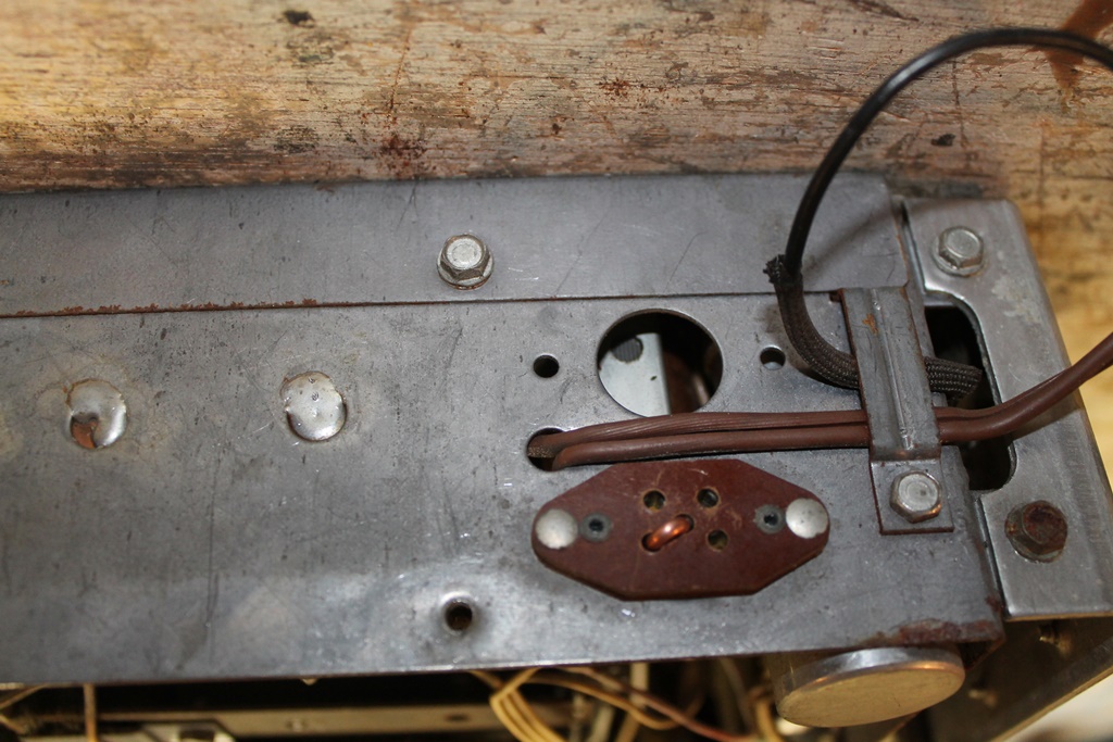
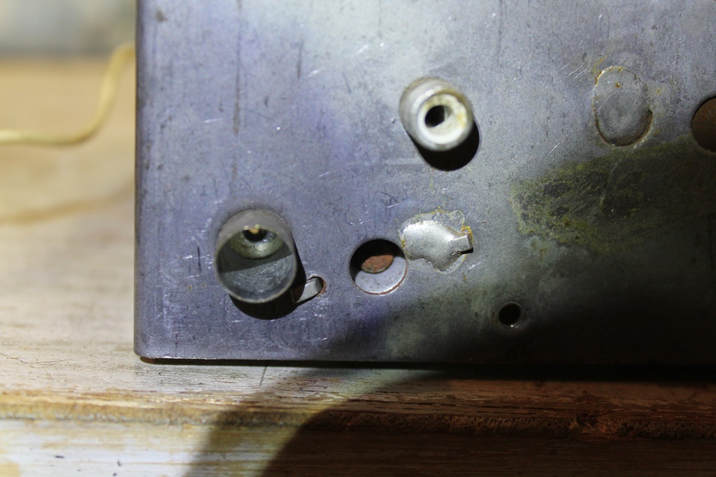
Antenna Trimmer: Usually next to the socket for the antenna (but
sometimes on the bottom of the radio) you will find a socket with a
screw inside, which is a variable capacitor inside the radio. If
the radio works well enough to receive stations, extend the antenna
to full height or at least 40 inches, and tune to a weak signal at
the upper end of the dial, around 1400khz. Using a small flat head
screwdriver, turn the antenna trimmer screw a little in each
direction until maximum volume is obtained. The capacitance on the
antenna lead-in cable is part of the tuned input circuit. If the
antenna or lead-in cable has been changed on the car, this procedure
must be performed to optimize reception. If a radio from a car with
a front antenna is transplanted to a car with a rear mounted power
antenna (or vice versa), this step is even more important. The
radios came pre-adjusted from the factory for optimum reception with
most front fender mounted antennas. If the car was ordered with a
rear mounted power antenna, the dealer was supposed to adjust the
antenna trimmer in the car for the longer antenna cable. If you
transplant a radio from storage or another car, always adjust the
antenna trimmer, Here is a photo with the location of the antenna
trimmer on a 1962 seven button radio, just to the right of the
antenna cable socket. Check your FSM for your specific radio.
At
this point if the radio is still “dead” or doesn't
perform well, it's time to remove it from the car and bench test it.
The FSM will have details on how to remove the radio.
Bench
Testing the Radio:
1. To bench test you will need a 12V+ volt power source (or 6V for
1955). Do not use a wall plug A/C adapter! You need a regulated
power supply like the ham radio guys use, or just use the car
battery or smaller tractor battery. You need a spare speaker; this
is a good use for an old Mopar “Deluxe” junk OEM
speaker. Any radio with transistorized audio output (1957 and
newer) MUST have a speaker connected before powering up the radio!
Also be sure to install the U-jumper correctly in the rear speaker
socket if not already present. You need a spare car antenna or just
a long wire to insert into the antenna socket as a temporary
antenna. You need a couple of alligator clip leads for connecting
the battery to the radio. See your FSM to determine which lead is
the 12V power connection. The battery negative connection goes to
the radio chassis/case, as seen in this photo.
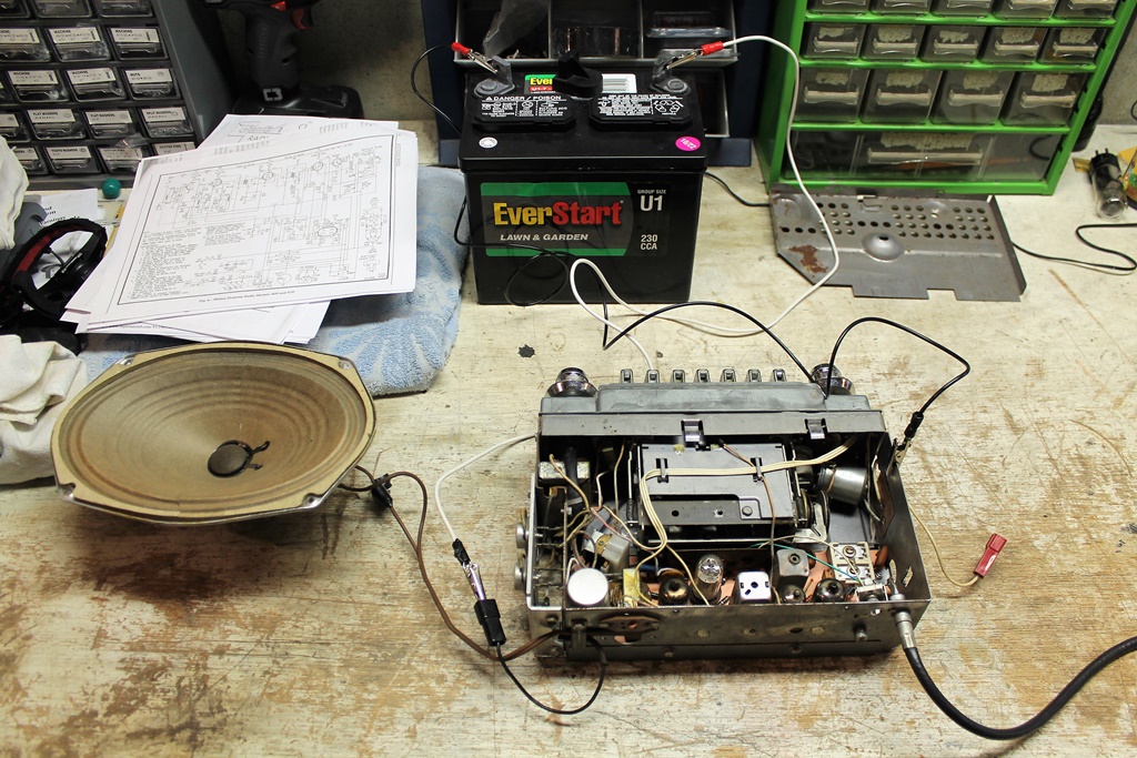
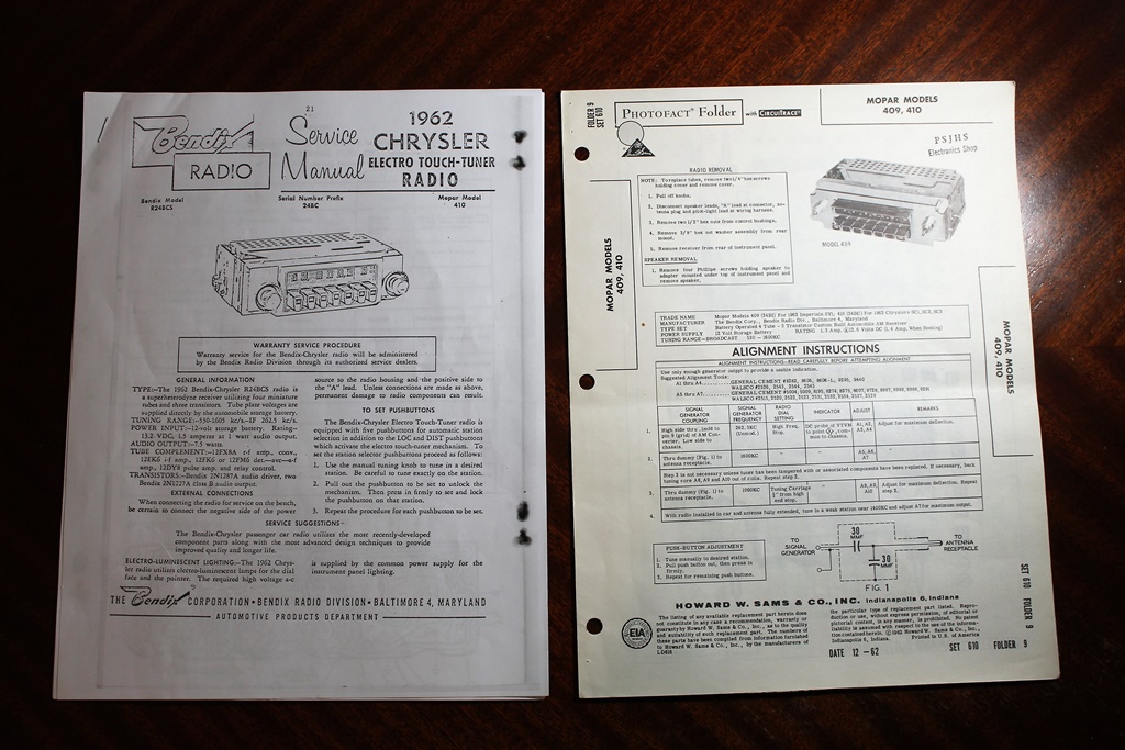
Get a schematic for the radio from the FSM, or better yet, a service
manual or Sams Photofact for the radio from ebay or the internet, as
seen here:
Common
Problems, Diagnosis, and Servicing:
1. Remove the top and bottom covers from the radio and examine the
internals for any obvious signs of burned wiring or components,
broken wires, modifications made in the past, or other major issues.
If the radio looks highly modified or badly damaged, it might be
wise at this point to send it to a professional radio guy or find a
better set.
2. Clean the controls. Get a can of Deoxit and spray some
inside the volume control, fader control, and other switches and
work them back and forth. This will help clear up any crackling or
static when the control is used.
3 Slipping tuning. The most common problem is the slipping
tuning knob clutch. You cannot change stations. The clutch normally
disconnects the tuning knob when you push a button. Thorough
cleaning (Qtip, some dish soap, and water) and applying powdered
rosin on the scuffed up rubber clutch disc might help. Also consider
adding a new spring that will pull the clutch fork tighter, toward
the outer radio case on the tuning knob side. The new spring can be
about 3/8 inch diameter by about one inch in length of small wire.
This might not be an easy job; so again consider if you are up to the
task. If the spring is too strong the buttons will stick; however,
at least you can manually tune the radio.
4. Electrolytic capacitors. The radio contains electrolytic
capacitors (e-caps) for filtering. If the radio has not been
powered up in years, and because these components are now 60 years
old or so, they are likely dried out and no longer work correctly.
Symptoms include hum, distortion, low volume output, no sound, and
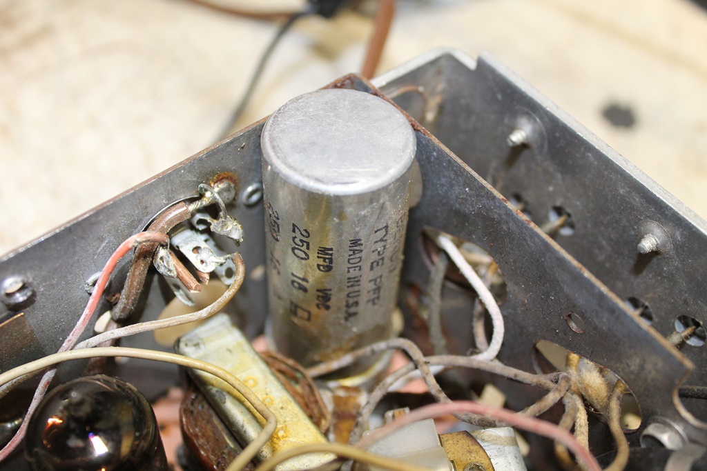
more. Back in the day e-caps were physically large and expensive.
The largest e-caps therefore were typically housed inside a round
aluminum can that was soldered to the circuit board. It contained 2
or 3 e-caps. Here is a photo of one in a 1962 seven button radio.
Some e-cap “cans” have been reproduced for the guys who
restore tube powered guitar amps, but they are expensive and
possibly not the correct capacitance/voltage that you need.
Attempting to remove the can from the 60 year old circuit board
could crack the board and damage the traces. So we therefore
install new individual e-caps in parallel in the circuit with the
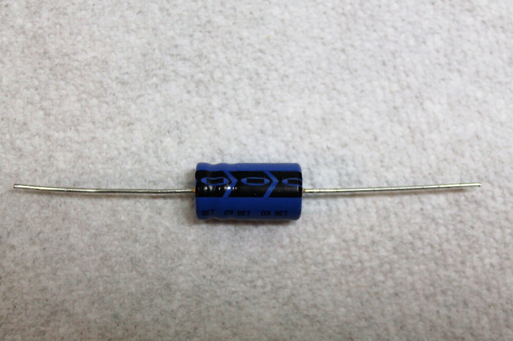
old ones in the can. E-caps are polarized (+ and -) and modern ones
are much smaller. Here is a photo of a modern e-cap. The arrows
point to the negative end.
In our car radios the e-caps are low voltage (typically rated for
16V) and the capacitance, expressed in microfarads (uf or mfd) is
perhaps 250uf to 1000uf. The exact capacitance is not critical.
You can go from perhaps 20% under to 80% or more over the original
amount. Some of the values, such as 250uf, are also obsolete and it
will be more expensive to obtain an exact replacement. You can
replace a 250uf e-cap with a 220uf e-cap (more common today) or even
a 470uf e-cap. The voltage rating, however, is more important. Do
not replace an e-cap with one rated at a lower voltage. For
example, do not use a 12V e-cap to replace a 16V e-cap. It is OK,
perhaps desirable, to obtain a new one with a higher voltage rating.
For example, you can use a 25V e-cap to replace a 16V. For the
tube and hybrid radios, pay the extra dollar to get 105 degree
Celsius rated caps vs. the standard 85C. The mobile environment is
harsh and tubes get hot.
It is said that the best e-caps are Japanese (Nichicon, Rubycon and
others). You do not need audiophile grade caps. Avoid generic
e-caps sold on ebay; some are Chinese junk, and may not be fresh
stock. New e-caps should be no more than a few years old; if they
have sat unused on a shelf for 10 years they are dried out. Order
them from a reputable, high volume supplier like Digi-Key or Mouser.
In most cases you want axial lead e-caps which are not as popular
these days. If you can fit radial lead e-caps in the radio you will
find a better selection at slightly lower cost for a given
capacitance. You will need the schematic and circuit layout in your
radio manual or Sam's Photofact to determine where to solder in the
positive leads. The negative side usually goes to chassis ground,
but not always – check the schematic! Space is also a problem
in car radios. You can place the e-caps in an open area and extend
the leads with insulated solid wire, such as 18ga. low-voltage
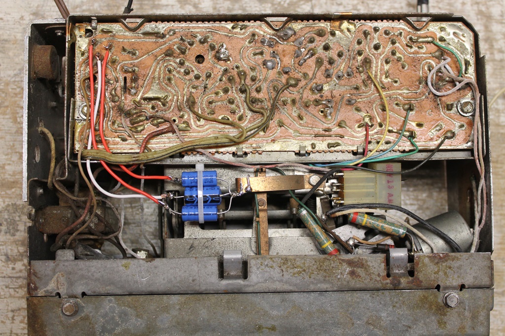
doorbell wire. After installing new e-caps, do not just put the
radio back on a shelf for 10 years or your new e-caps will go bad.
Power the radio up at least every 6 months. Here is a photo of new
e-caps installed in a 1962 radio:
5. Output Transistor(s). Properly working output
transistors should get warm after a few minutes, and if the radio is
equipped with two of them they should both be the same temperature.
The output transistor(s) can fail, typically from a short, in which
case they will stay cold to the touch. The emitter lead wire
(actually a special type of resistor) will appear burned up on the
shorted transistor. If the radio has two output transistors, the
second lead will burn up as well due to overload. Always replace
both output transistors at the same time, even if only one is bad.
You can use modern silicon PNP transistors (NOT the more common NPN
type!) as replacements, if you feel confident with this level of
repair. Otherwise, send the set to a radio guy. Germanium PNP
transistors are also now available on ebay. On the radios with two
output transistors, it is CRITICAL to use identical transistors –
ensure that every marking on the two transistors is identical.
Mount them with mica washers and silicone heat conductive grease to
a clean aluminum surface. If the emitter wire has burned open, it
is OK to shorten it to no less than 90% of its original length via a
splice or added wire, but you must do this to both emitter leads.
If you use silicon PNP replacement transistors, a critical part of
the installation is to set the bias (either via the adjustable bias
resistor near the transistors, or replacing the fixed bias resistor
if so equipped). You will need to adjust the resistor substantially
to obtain the recommended 80-100ma of collector current needed for
the new transistors. If a fixed resistor is used, solder it
securely to the underside of the circuit board after cutting off the
original. Use a 1 watt resistor (½ watt is ok if over 1000
ohms). To set the collector current via the bias adjustment, tie
both transistor cases together via a jumper and connect a DC meter
from the jumper and cases to the two leads removed from the case
screws (two leads shorted together). Adjust the bias to a reading
of 80-100ma on the meter. Failure to do this will result in
overheating of the junction as you cruise along and – poof! -
you are back to ground zero with burned out transistors!
One advantage of using the germanium transistors is that the bias
adjustment may not be necessary, which saves time and effort.
6. Printed circuit board. The circuit board can crack or
break right at the connection of a heavy component such as the audio
transformer or the e-cap can. This causes strange events, especially
sensitivity to vibration as you hit a bump. You often cannot see
the crack in the board! Best remediation is to carefully re-solder
the connections and mounts. Use caution – the board is old.
7. Power switch. Usually on the volume control
(potentiometer). Replace or jumper the switch. If you jumper the
switch the radio will be on all the time. No different than modern
Mopar radios in that regard – you can turn down the volume (or
mute) but cannot turn them off.
8. Tubes (aka “valves” ). The 1955-56 radios
were tube powered. The 1957 -62 radios were all hybrids –
tube powered with transistorized audio output. The 7 button AM
radios remained hybrids through 1964. The 5 button radios became
100% transistorized starting in 1963. The AM-FM radios were all
100% transistorized. 90% or more of the time the original tubes are
still good. Generally speaking, tubes are the LEAST likely of your
radio problems. When you power the radio up, check for light inside
the tube as the filament heats up. Some tubes are dark or opaque;
in that case feel the tube for warmth on the surface as the tube
heats up (allow 5 or more minutes). A tube with no vacuum will get
warm but will not light up. Substitution of a good used tube is the
easiest way to check a suspected bad tube. Used tubes are available
on ebay.
The tube pins can corrode and oxidize in the tube sockets. Remove
all the tubes – use care and remove gently – a very
small screwdriver under the glass may help lift the tube from the
socket. Being too aggressive can also damage the old circuit board
on which it is mounted. Slow and steady wins the race here. After
removing the tube, clean the pins with Scotch Brite. Straighten any
bent pins. Using a Qtip or toothpick, apply a little silicone
dielectric grease to each pin. Reinstall each tube all the way into
their correct sockets.
9. Dial Lights Replace the dial lights (if so equipped)
with new ones. The 1960-62 radios used Electroluminescent dial
lighting. You can check the EL lighting by connecting the lead to
the EL system in the car. A properly operating EL power pack is
required. The EL radio dial lighting does NOT light up unless the
radio is turned on, with the headlight switch on.
10. Search Tune feature on 7 button radios. Fuhgeddaboudit.
On the 1960-64 Bendix AM 7 button radios, they went and spoiled a
great set with a poorly designed power tuning system with the
reliability of a Chevy Vega. Or maybe worse. These radios use a
complicated snap over reversing switch that can break mechanically
and cannot be repaired – the contact leafs just snap off. The
best advice is to give up and cut the wire to the motor, or just
avoid pressing the “local” or “distant”
buttons. The radio will work fine and dandy using manual tuning.
It is possible to replace the system with modern IC's and a relay –
but huge effort – and maybe a 50% success rate as the motor or
clutch is often bad. The motor seizes, and the electric clutch
wears out, or fine wires inside the power drive clutch break off.
These are excellent radios for sound and sensitivity when “right”
- enjoy them by tuning manually. And they look cooler in your
F/G/H/J/K than the 5 button radios, right?
11.
1F tuning transformers.
The IF (intermediate frequency) caps are located inside square
aluminum cans (typically 2 of them) mounted on the circuit board.
These cans contain mica sheets with silver on them and are open to
air. You know what happened to grandma's silver when it sat out –
it tarnished! The silver in these cans does the same thing –
turns black over time – and manifests as weak pick up and
jumping volume on bumps. If you determine that an IF transformer is
bad, the best answer is to send the set to a radio guy or get a
different radio – these are very difficult to fix. Some old
tube radios – notably Zeniths – had such a problem with
these silver mica transformers that the antique
radio guys coined a term for it: “silver mica disease.”
The radio would sound like a terrible lightening storm was
occurring – on a clear, sunny day.
12.
Radio alignment. The
radio service manual or Sam's Photofact will contain a complicated,
very EE centric procedure for “aligning” (i.e.
electronically tuning and calibrating) the radio using a signal
generator and other special equipment. This is beyond the DIY skill
set unless you are a certified “radio guy.” However,
with the AM radios you can “align by ear” and possibly
get better results than going through the gobbledigook (that's a
technical term) procedure in the manual. We have already discussed
the antenna trimmer earlier, which is the final alignment step. The
IF transformers can be adjusted, if you have the correct radio
alignment tools (available on ebay), although the alignment points
are not always easily accessible. See your Photofact or manual for
the layout and location. The Bendix radios have two easily
accessible, screwdriver adjustable, variable capacitors on the
chassis that can be adjusted by ear for optimal results. One for
the oscillator and the other for the RF. Tune the radio to a weak
station around 700 – 800kHZ and begin with the OSC
(oscillator). This one should not require much, if any, adjustment.
Then adjust the RF. That one may improve reception through
adjustment to the left or right. Adjust for maximum signal/volume.
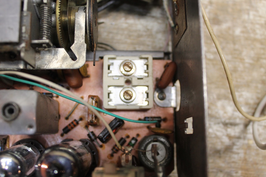
Here is a photo of these components in a 62 seven button radio. You
can also see one of the IF transformer cans on the left side of the
photo.
On
the Delco AM-FM sets from 1963-65, it is risky to attempt to align
the FM section “by ear” - or for that matter on any FM
radio or stereo. FM alignment must be precise and is tricky –
best left to a professional radio guy.
13.
Tuner section. Leave it
alone! Do not EVER take apart the tuner, as the setting of the
tuning slugs and tracking is impossible without elaborate test
equipment.
|