|
1960-1964
“Golden Touch Tune” Search-Tune 7 Button Bendix AM
Chrysler Radios –
The
1960-64 Chrysler “7 button” AM radios were produced by
Bendix, and offered power search tune capability, as opposed to the
less expensive “5 button” radio. They were marketed as
the “Golden Touch Tune” radio whereas the “5
button” radio was marketed as “Golden Tone.” For
1960-62, the Golden Touch designation was used on the radio dial, but
that designation was absent in the narrower, simpler dial face
presentation used in 1963-64.
The
front dial/pushbutton cosmetic appearance of the radios was changed
each model year through 1963, but the physical chassis and electronic
circuits remained nearly identical from 1960-64. They were all
hybrid radios, using 4 vacuum tubes for the radio section, one PNP
transistor for the audio driver, and a matched pair of PNP
transistors for audio output. For each model year, the Chrysler
radio was also electronically identical to the Imperial version of
the radio, but they were different cosmetically. Because they were
the same electronically, both versions of the radio are covered
together in some of the radio service manuals. The exception is
1963, where the Imperial version of the radio still used
electroluminescent dial lighting, but the Chrysler version used
incandescent bulb dial lighting. For each year, the radio was
available with a front speaker, or both a front and rear speaker at
additional cost for the hardtops, except when dual A/C was available
and ordered. On the convertible the rear speaker was not available
until 1963, but since there was no 300J convertible, the first letter
car convertible that offered this radio with a rear speaker was the
1964 300K.
We
will examine each model year separately, and illustrate some of the
cosmetic and electronic changes by model year. Please refer to our
introductory page about radios for general information and servicing
tips here: https://chrysler300club.com/tech/radio/1.html
Let's
first look at some new information regarding service and operation of
these particular radios that was not covered in the introductory
page.
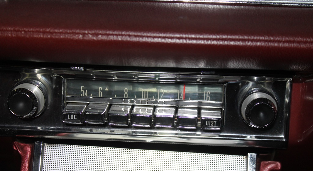
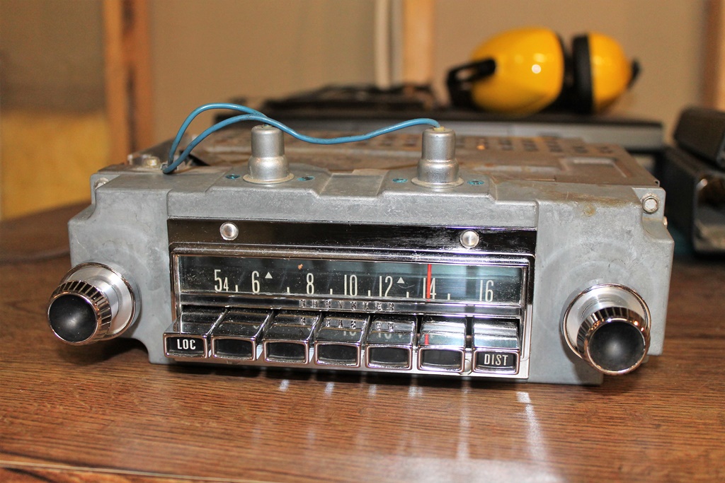
Rear
speaker socket and fader control:
On these 7 button radios, the jumper must be installed in the proper
pins in order to function, and it is different than what is shown in
the FSM (the FSM shows where to install the jumper on the 5 button
radio). On the 7 button radio, the jumper must be installed between
pin #3 and the center pin, as seen in the photo here of the rear of
the radio:
Also, note the hole in the chassis above the rear speaker socket.
This was for a phono socket, and was used only when a record player
was installed in the car.
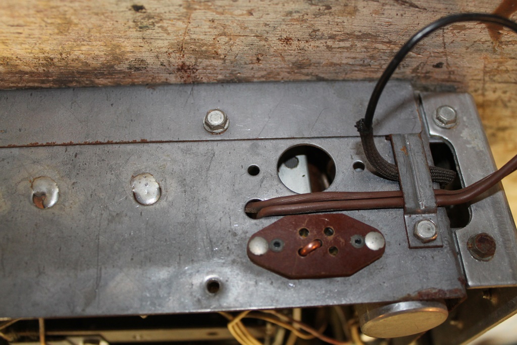
Because those aforementioned resistors were installed on the fader
switch, an elusive potential problem has been discovered during
servicing the radio receiver. When the front panel is removed and
reinstalled, care should be taken to ensure that those resistors do
not accidentally short to one another or to the metal front panel.
They are metal encased and covered with fabric insulators can can
slip off. Here is a photo showing these resistors, where they have
managed to short because they are touching one another. If this
happens, the radio volume output will be greatly diminished. Ask me
how I know this!
Power
Output and Speakers:
For each of these model years the radio was advertised as having 7.5
watts of audio output. This was before power output was more
accurately specified as RMS output at a certain impedance, at a
certain rate of distortion, which became more standardized later in
the 70's and 80's. So take the stated output with a grain of salt,
as it is nowhere close to 7.5W RMS. Frequency response of the radio
is not stated, but seems quite good for an AM set. For each model
year, Mopar “Deluxe” 6”x9” speakers were used
rated at 3 to 4 ohms.
When using modern speakers as replacements, choose something simple,
such as the Metra brand replacement speaker (available from NAPA
under Audiovox brand, or other online sites at lower cost) or the
“factory radio” brand. Costly triaxial speakers designed
for modern car stereos are not needed and will not provide better
sound.
Now let's examine the radio offered each model year.
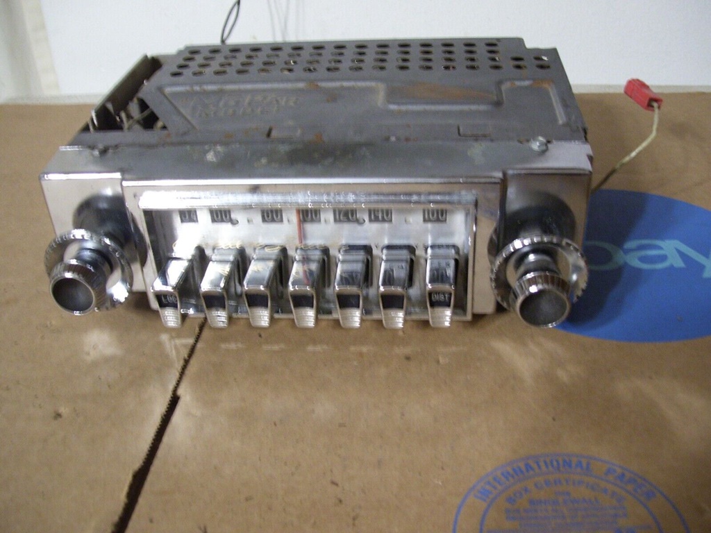
1960
The 300F “Golden Touch Tune” radio was model 403,
available with front speaker only as sales code 423, or with both
front and rear speaker as sales code 428. 52.5% of 300Fs were
equipped with this radio (42.8% had the 5 button radio, and 4.7% were
ordered without a radio).
1960 used a “smooth” dial face, as seen in this photo.
While this radio is actually a 5 button set, it is the same dial face
as the 7 button set, and is a good photo to illustrate the dial face
design:
Here is a photo of the 1960 seven button set, albeit a little blurry.
Note that the radio knobs are painted black in the center.
The dial was lit by the car's electroluminescent power pack, which is
connected to the white wire as seen in the photo above.
The radio used 4 tubes: 12FX8 RF amp/converter, 12EK6 IF amp, 12AE6A
detector/AVC/AF amp, and 12DY8 trigger relay control. The audio
driver was a 2N1287 transistor, and the audio output used a matched
pair of 2N1227 transistors.
1961
The 300G “Golden Touch Tune” radio was model 407,
available with front speaker only as sales code 423, or with both
front and rear speaker as sales code 428.
The radio knobs were painted black in the center. 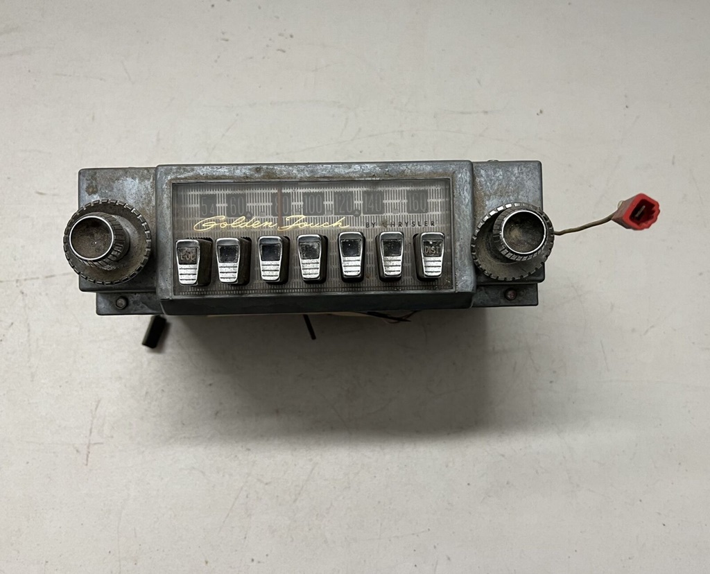 The radio used 4 tubes, same as 1960 except that the RF amp used an updated 12FX8A tube, and the detector/AVC/AF amp was changed to a 12FK6 or 12FM6 tube. All three transistors were upgraded with new “A” suffix versions of their 1960 counterparts. 1962
The 300H “Golden Touch Tune” radio was model 410,
available with front speaker only as sales code 363, or with both
front and rear speaker as sales code 365. We do not have all the
300H records, but of those we have, 52.9% were equipped with this
radio (42.1% had the 5 button radio, and 5.0% were ordered without a
radio).
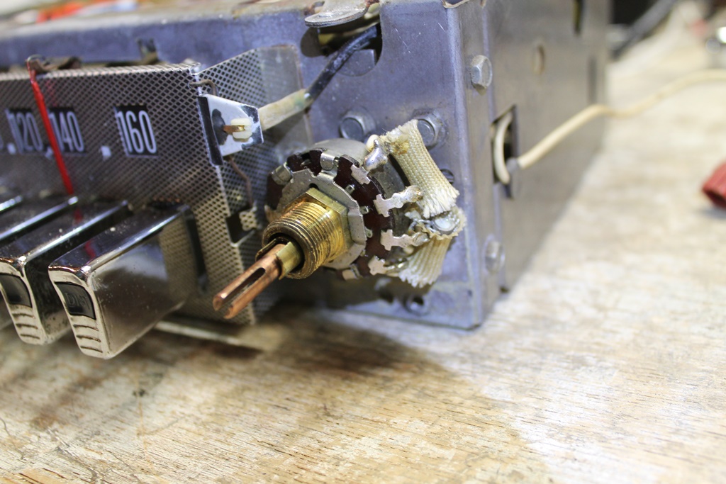
1962 used a triangle design on the dial face and was the last year to be lit via the electroluminescent power pak. For more on the differences on the dial faces, click here. The radio knobs had chrome centers. 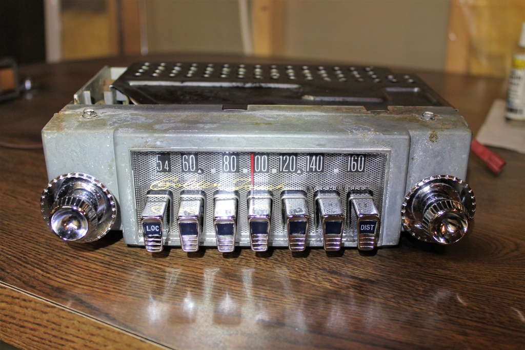
Electronically, the 1962 radio was essentially a carryover from 1961, with the same tubes and transistors. 1963
The 300J “Golden Touch Tune” radio was model 411,
available with front speaker only as sales code 363, or with both
front and rear speaker as sales code 365. 46.0% of 300Js were
ordered with this radio (46.8% had the 5 button radio, 2.5% had the
new AM-FM radio, and 4.8% were ordered without a radio).
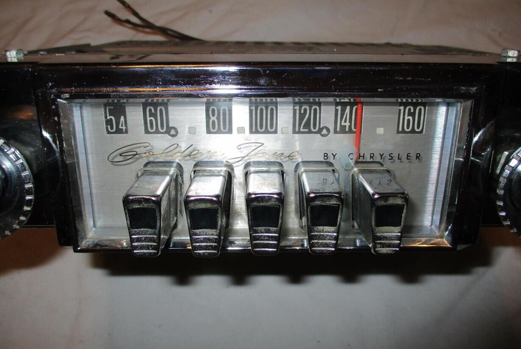
Cosmetically, the 1963 version of this radio looked all new. The
dial face, pushbuttons, and tone and fader controls were completely
redesigned. The volume and tuning knobs, however, were identical to
the 1960-61 style with black painted centers. The 1963 radio dial
was lit by two type 53X incandescent bulbs.
While the 1963 version of the radio looked all new, electronically it was a carryover of the 1962 model with the same tubes and transistors. There were some very minor changes in the physical layout of the internal circuits/wiring, but nothing of significance. 1964
The 300K “Golden Touch Tune” radio was model 415,
available with front speaker only as sales code 366, or with both
front and rear speaker as sales code 367. The rear speaker could be
ordered in a convertible, making the 300K the first letter car
convertible that could be equipped with a rear speaker.
Cosmetically and electronically, the 1964 version of the radio
appears to be identical to 1963. 1964 was the last year for the
hybrid tube/transistor 7 button radio.
|